TOP Contributors

  1. MIKROE (2784 codes)
  2. Alcides Ramos (387 codes)
  3. Shawon Shahryiar (307 codes)
  4. jm_palomino (120 codes)
  5. Bugz Bensce (97 codes)
  6. S P (73 codes)
  7. dany (71 codes)
  8. MikroBUS.NET Team (35 codes)
  9. NART SCHINACKOW (34 codes)
  10. Armstrong Subero (27 codes)

Most Downloaded

  1. Timer Calculator (140170 times)
  2. FAT32 Library (72626 times)
  3. Network Ethernet Library (57645 times)
  4. USB Device Library (47958 times)
  5. Network WiFi Library (43556 times)
  6. FT800 Library (42943 times)
  7. GSM click (30141 times)
  8. mikroSDK (28672 times)
  9. PID Library (27058 times)
  10. microSD click (26553 times)
Libstock prefers package manager

Package Manager

We strongly encourage users to use Package manager for sharing their code on Libstock website, because it boosts your efficiency and leaves the end user with no room for error. [more info]

< Back
mikroSDK Library

RMS to DC click

Rating:

7

Author: MIKROE

Last Updated: 2019-01-16

Package Version: 1.0.0.0

mikroSDK Library: 1.0.0.0

Category: Measurements

Downloaded: 4584 times

Not followed.

License: MIT license  

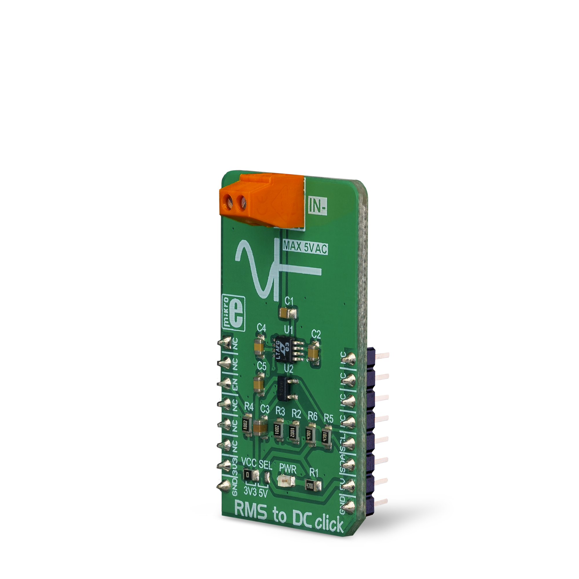
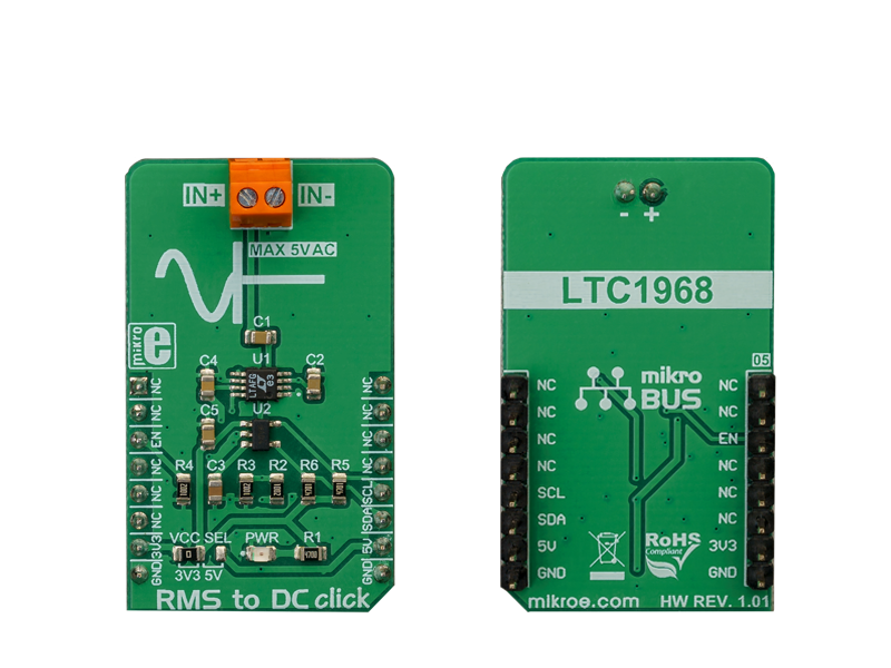
RMS to DC click is a Click board that is used to convert the RMS of the input signal into a DC voltage, with a value directly readable over the I2C interface. The Click board is equipped with the LTC1968, an RMS-to-DC converter IC, which outputs an analog voltage depending on the RMS value of the input signal.

No Abuse Reported

Do you want to subscribe in order to receive notifications regarding "RMS to DC click" changes.

Do you want to unsubscribe in order to stop receiving notifications regarding "RMS to DC click" changes.

Do you want to report abuse regarding "RMS to DC click".

  • mikroSDK Library 2.0.0.0
  • Comments (0)
DOWNLOAD LINK RELATED COMPILER CONTAINS
mikroBasic PRO for ARM
  • lib
  • src
  • exa
  • hlp
  • hex
  • sch
  • pcb
  • doc
mikroBasic PRO for AVR
  • lib
  • src
  • exa
  • hlp
  • hex
  • sch
  • pcb
  • doc
mikroBasic PRO for dsPIC30/33 & PIC24
  • lib
  • src
  • exa
  • hlp
  • hex
  • sch
  • pcb
  • doc
mikroBasic PRO for FT90x
  • lib
  • src
  • exa
  • hlp
  • hex
  • sch
  • pcb
  • doc
mikroBasic PRO for PIC
  • lib
  • src
  • exa
  • hlp
  • hex
  • sch
  • pcb
  • doc
mikroBasic PRO for PIC32
  • lib
  • src
  • exa
  • hlp
  • hex
  • sch
  • pcb
  • doc
mikroC PRO for ARM
  • lib
  • src
  • exa
  • hlp
  • hex
  • sch
  • pcb
  • doc
mikroC PRO for AVR
  • lib
  • src
  • exa
  • hlp
  • hex
  • sch
  • pcb
  • doc
mikroC PRO for dsPIC30/33 & PIC24
  • lib
  • src
  • exa
  • hlp
  • hex
  • sch
  • pcb
  • doc
mikroC PRO for FT90x
  • lib
  • src
  • exa
  • hlp
  • hex
  • sch
  • pcb
  • doc
mikroC PRO for PIC
  • lib
  • src
  • exa
  • hlp
  • hex
  • sch
  • pcb
  • doc
mikroC PRO for PIC32
  • lib
  • src
  • exa
  • hlp
  • hex
  • sch
  • pcb
  • doc
mikroPascal PRO for ARM
  • lib
  • src
  • exa
  • hlp
  • hex
  • sch
  • pcb
  • doc
mikroPascal PRO for AVR
  • lib
  • src
  • exa
  • hlp
  • hex
  • sch
  • pcb
  • doc
mikroPascal PRO for dsPIC30/33 & PIC24
  • lib
  • src
  • exa
  • hlp
  • hex
  • sch
  • pcb
  • doc
mikroPascal PRO for FT90x
  • lib
  • src
  • exa
  • hlp
  • hex
  • sch
  • pcb
  • doc
mikroPascal PRO for PIC
  • lib
  • src
  • exa
  • hlp
  • hex
  • sch
  • pcb
  • doc
mikroPascal PRO for PIC32
  • lib
  • src
  • exa
  • hlp
  • hex
  • sch
  • pcb
  • doc

mikroSDK Library Blog

RMS to DC click

RMS to DC click

Native view of the RMS to DC Click board.

View full image
RMS to DC click

RMS to DC click

Front and back view of the RMS to DC Click board.

View full image

Library Description

The library performs an RMS to DC signal converting with 12bit resolution. It is also possible to get the averaged output DC signal (voltage), with a minimalized noise. For more details check the documentation.

Key functions:

  • uint16_t rms2dc_readADC( void ) - The function returns a 12bit result of AD conversion.
  • T_RMS2DC_V rms2dc_voutADC( T_RMS2DC_V vccSel ) - The function returns the output voltage value calculated to mV, depending on the power voltage selection.
  • T_RMS2DC_V rms2dc_avrgVoutADC( T_RMS2DC_V vccSelect, uint8_t nSamples ) - The function returns the averaged output voltage value calculated to mV, depending on the power voltage selection.

Examples description

The application is composed of the three sections :

  • System Initialization - Initializes peripherals and pins.
  • Application Initialization - Initializes I2C interface and turns ON the device.
  • Application Task - (code snippet) - Reads averaged DC output voltage calculated to mV, and sends results to the serial plotter. Note: The input voltage frequency should be in the range from 50Hz to 250kHz. Als,o the input voltage amplitude must be lower than 5V. In these conditions, the device can convert the RMS signal, in every form, to DC signal.
void applicationTask()
{
    outVoltDC = rms2dc_avrgVoutADC( _RMS2DC_VCC_3V3, 25 );
    
    plotData( outVoltDC );

    Delay_ms( 5 );
}

Additional Functions :

  • void plotData( T_RMS2DC_V plotY ) - Sends data (DC voltage) to the serial plotter.
  • void logData() - Sends DC voltage value to the uart terminal.


Other mikroE Libraries used in the example:

  • Conversions
  • I2C Library
  • UART Library

Additional notes and information

Depending on the development board you are using, you may need USB UART click, USB UART 2 click or RS232 click to connect to your PC, for development systems with no UART to USB interface available on the board. The terminal available in all MikroElektronika compilers, or any other terminal application of your choice, can be used to read the message.

ALSO FROM THIS AUTHOR

Flash 11 Click

0

Flash 11 Click is a compact add-on board representing a highly reliable memory solution. This board features the AT25SF321B, a 32-Mbit SPI serial Flash memory with Dual I/O and Quad I/O support from Dialog Semiconductor. It is designed for applications in which the program code is shadowed from Flash memory into embedded or external RAM for execution and where small amounts of data are stored and updated locally in the Flash memory. It has a flexible and optimized erase architecture for code and data storage applications, non-volatile protection, three specialized protected programmable 256-byte OTP security registers, and a 64-bit factory programmable UID register.

[Learn More]

DC Motor 12 Click

0

DC Motor 12 Click is a compact add-on board with a brushed DC motor driver. This board features the TB9054FTG, a PWM-type, dual-channel, H-bridge, brushed DC motor driver from Toshiba Semiconductor. The TB9054FTG is rated for an operating voltage range from 4.5V to 28V, with the motor controlled directly through a PWM signal or SPI serial interface. In addition, this driver allows a dual configuration with two motors with 5A current ratings per channel or one 10A channel drive in a Parallel mode of operation. It also has complete diagnostic and protection capabilities supporting robust and reliable operation.

[Learn More]

7-SEG RGB Click

0

7-SEG RGB Click carries a full color single 7 segment digit display. The Click is designed to run on either 3.3V or 5V power supply. It communicates with the target microcontroller over the CS, and PWM pin on the mikroBUS™ line.

[Learn More]